

I generally try and use Copley motor controllers whenever I can. This is for several reasons including:
- Reliability
- Linux software API (for a small fee) which can easily be wrapped for using in ROS
- Copley, if you are reading this you should make CML available to everyone for free…
- Same software API for a wide range of different controllers (AC, DC, brushed, brushless, stepper, little motors, big motors, etc…)
- Excellent support
- Flexible and easy to use interface for bringing up new systems
This has led many others that I have worked with over the years to choose Copley controllers and then ask me how to configure them. This post is a guide to bringing up a new system using Copley motor controllers.
Note/Disclaimer: I am embedding many videos in this post. They are not required to watch for this, but they are informative. I will also be honest and admit that I have not fully watched these videos…
1. Properly Wire the Motor Controller
Each controller has its own wiring guide. Other than saying that you should follow the wiring guide for the drive you have, here are a few thoughts:
- Purchase cable and/or connector kits from the manufacturer. For non-production systems this will make your life much easier (although it does cost more).
- Purchase one more connector kit than drives. Just in case…
- The basic items that must be wired are:
- Power
- Motor
- Encoder and/or Hall feedback (can be on motor and/or load)
- STO (Safe Torque Off) and/or Enable. Not all drives have an STO, if the drive has an STO but you want to use the enable line, there is a jumper that can be used to disable the STO
- Communications (Serial, CAN, etc..)
- For CAN make sure the last device is terminated, and the CAN converter card has a termination resistor
- The Copley CAN cards have an internal jumper to set termination (Copley could do a better job documenting this…)
- For CAN make sure the last device is terminated, and the CAN converter card has a termination resistor
- Other common items:
- Limit switches (if applicable)
- Temperature sensor for the motor (many motors do not have this)
- Generally for robotics where we have a computer controlling the motors, you will want to use CAN to control multiple axis (axis is the fancy word for motor)
- If you are connecting the drives to your computer, do NOT use EtherCAT (I dont care what motor controller vendors tell you). There are a lot of extra things to think about for EtherCAT (maybe this should be a future post…).
- Try to purchase the CAN adapter from Copley.
- They work
- They have Linux and Windows drivers
- When/if you have a problem, Copley cant complain about using a 3rd party CAN device.
- Also order the CAN connector kit when ordering the adapter
- Not directly related, but figure out if you will need a shunt regulator (or a shunt resistor on your controller)
2. Connect via Serial Port to Each Controller (if CAN is configured you can use CAN to do most of the steps below on each drive).
- Download the CME2 program to configure the drives https://www.copleycontrols.com/en/software/
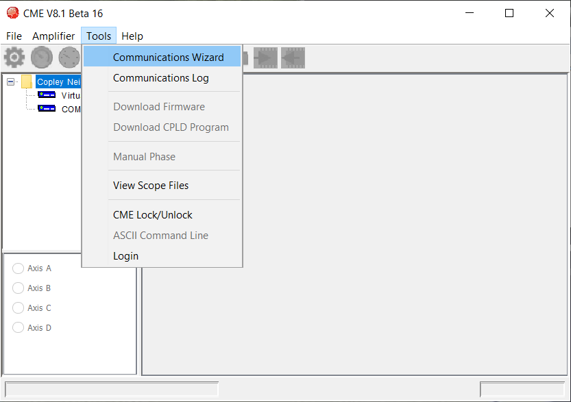
- Goto Tools>Communications Wizard
- If you can not connect, restart CME, CME often has a problem if devices are plugged in while CME is running.
- In Windows: Goto Device Manager and check “COM and LPT Ports” to verify the device is plugged into the computer and what its port name is
- For a CAN converter make sure you have the CAN device driver installed
- With Linux the kernel module often gets uninstalled, and needs reinstalled (check if the device in /dev exists). Also the permissions must be set correctly (ex. sudo chmod 777 /dev/copleycan00)
- Make sure the CAN network is terminated
- The nice thing with CAN is that all your drives will show up in the left column.
- Just make sure all CAN ID’s are unique as you bring up and configure things.
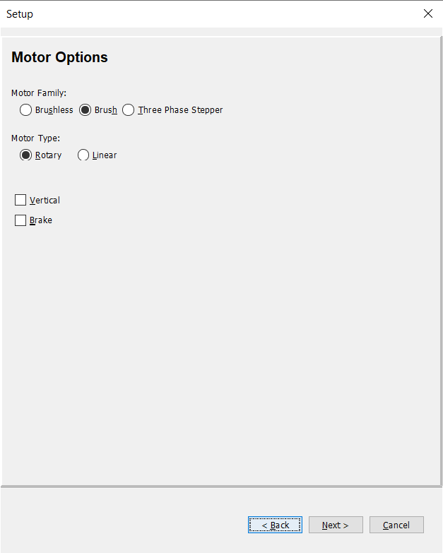
3. Run the Setup Wizard
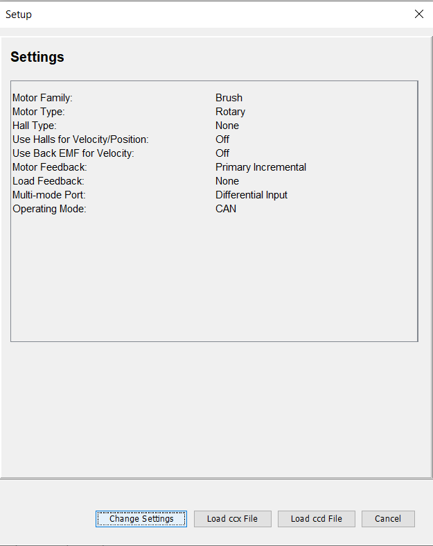
The setup wizard is the basic place where you setup the drive settings. This includes things such as motor type, encoder type, and command modes. We will configure the motor settings later.
In Amplifier->Setup, select the “Change Settings” button. Then follow the wizard.
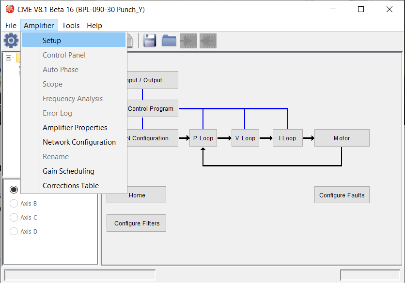
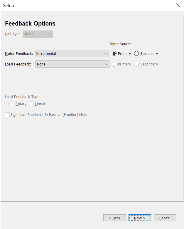
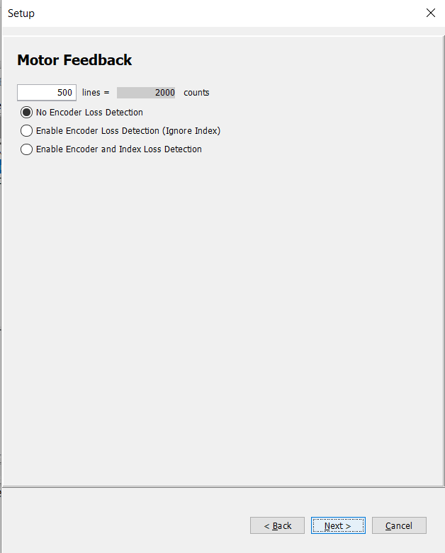
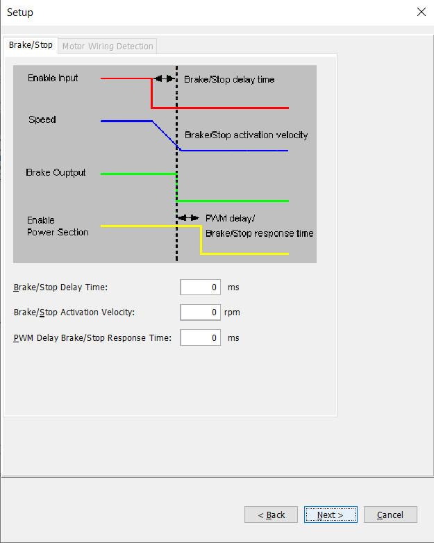
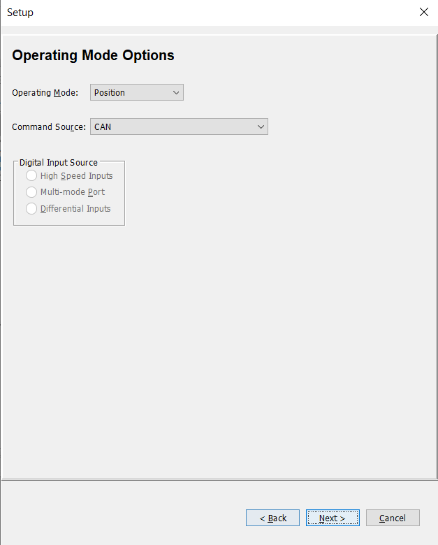
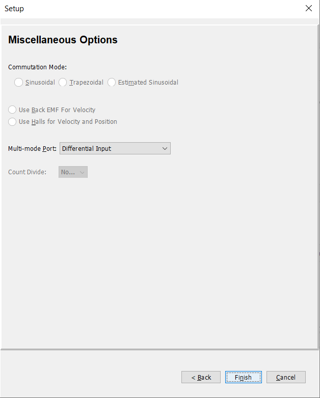
Click Finish and we are ready to move to the next step.
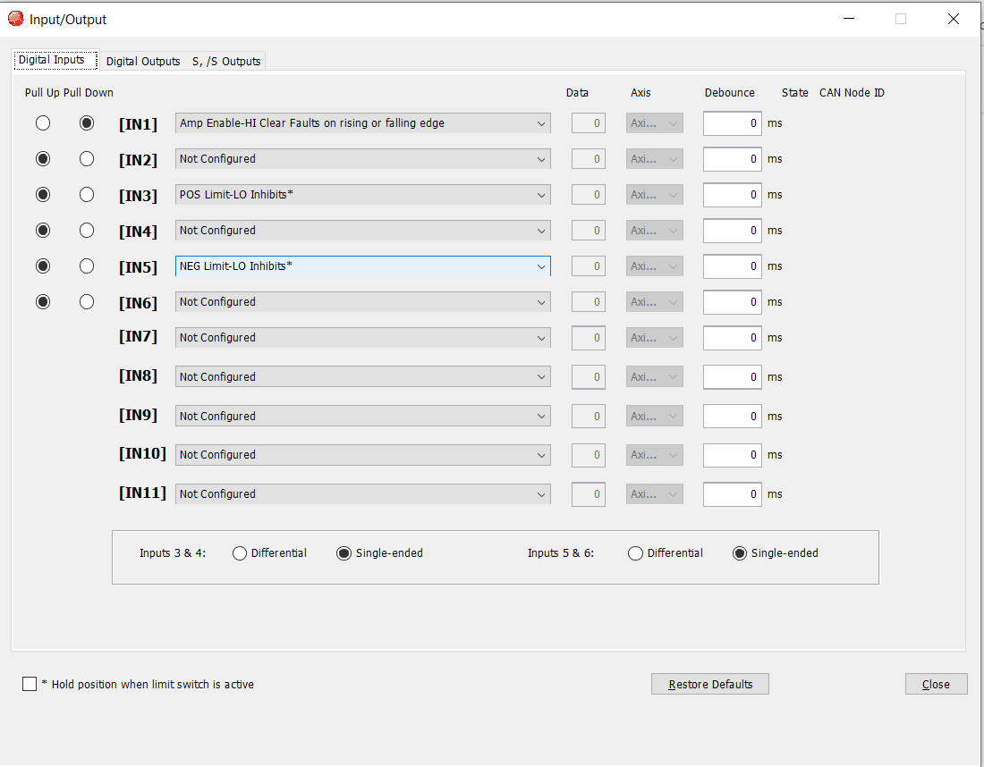
4. Configure I/O
- Select the Input / Output tab on the flow diagram to configure limit switches, enable switches, temperature switches, etc..
- Some inputs can be Pulled Up or Pulled Down based on how your system is wired.
- If you have a common enable bus, all drives need to be configured the same for this to work properly.
- There is an option for debouncing that is often good in case there is noise on the enable line that causes spurious e-stops.
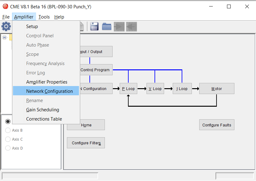
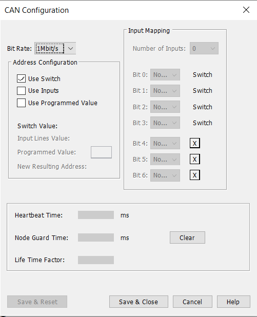
5. Configure Network (ie. CAN)
Assuming you are using CAN to network all your devices, we can configure that next. On some drives you set the CAN ID here, on other drives you have a choice to also use switches on the drive.
If you have a firmware for each drive you can manually set each CAN ID, if you want one config file for all drives then use the switches to set CAN ID.
To configure these CAN settings goto Amplifier->Network Configuration
You will need to reboot the drive for these changes to take effect.
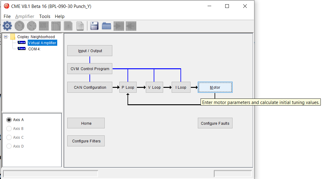
6. Motor Config
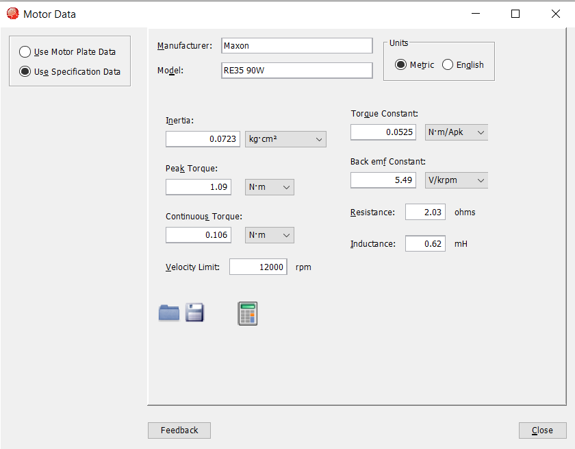
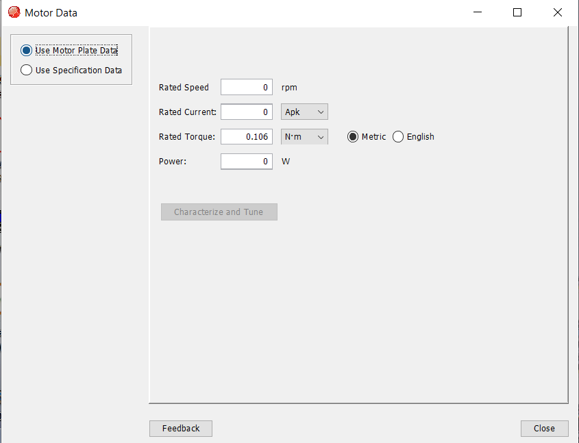
This is where we finally get to tell the drive about the type of motor we have connected. Some motor vendor datasheets give you all of the information for this, other motors can be difficult to get these values and you might have to guess a bit. There are two ways to enter these values, both approaches will be shown below.
Pro Tip: Be careful with units. Motor datasheets are often in different units than what the Copley Motor page wants.Over time I have developed a library of motor config files so I can often reuse motor values and save time in not having to re-find all these values for every project.
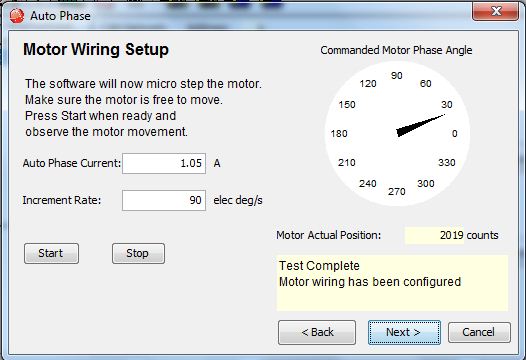
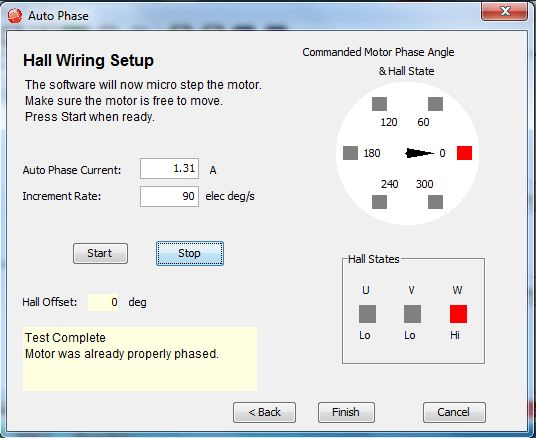
7. Auto Phase Wizard
The Copley drivers can figure out how the motor phase labels correspond to driver phases. So lets run a wizard to figure this out and then check basic commutation. This will also allow you to set which direction of the motor spinning is considered positive (and which direction is considered negative).
This should ideally be run with no load attached to the motor.
Goto Amplifier->Auto Phase
Pro Tip: If you need to change the direction of motion in the future (after running this wizard), this can be done by inverting motor and/or feedback on the Tools-> Manual Phase page.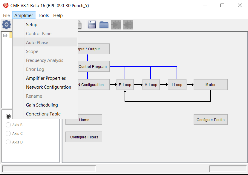
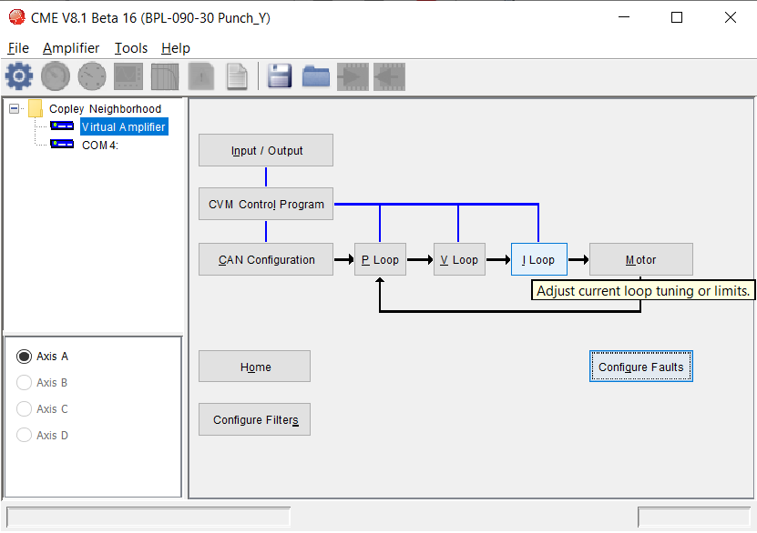
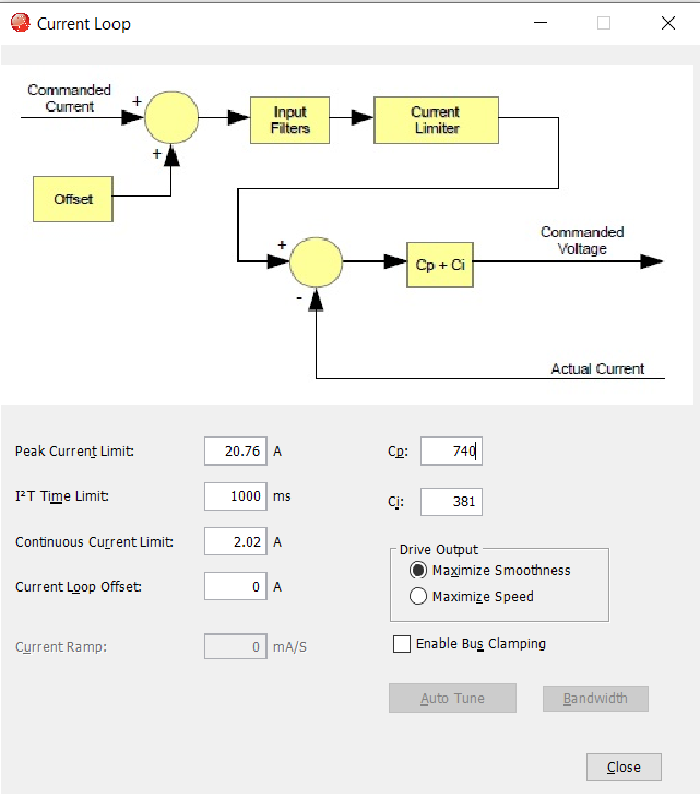
8. Current Loop Auto Tune
The next step is to tune the current loop of the drive.
- On the main page select the I Loop button
- Verify the continuous and peak currents are correct
- Click the Auto Tune button to automatically figure out what the current gains should be.
- The motor will make singing noises while this happens
- In the Autotune results you want a bandwidth of around 1kHz (+/-200Hz)
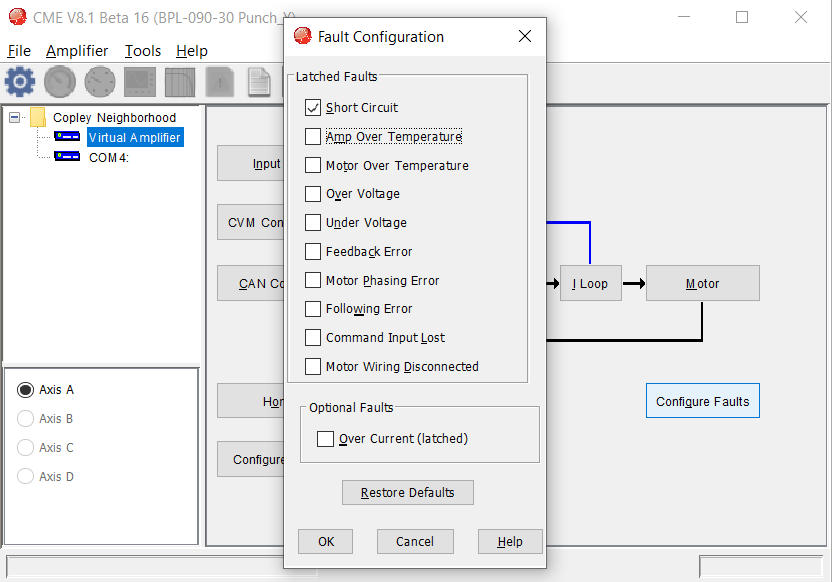
9. Configure Latching Faults
I generally dont like latching faults since I just want my robot to work. You are free to set these how you please. See below for how I usually configure the latching faults.
Select the Configure Faults button from the main page.
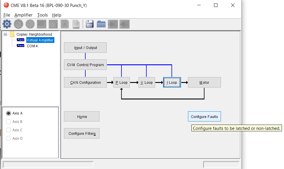
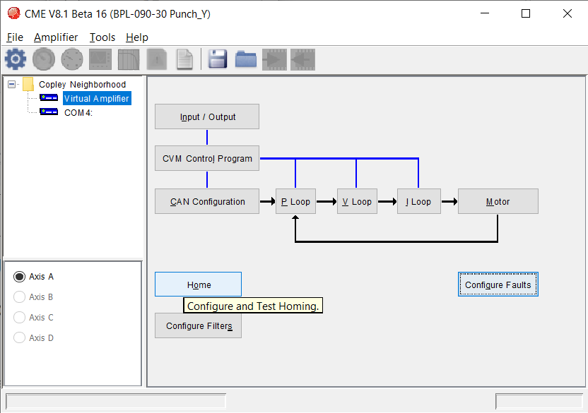
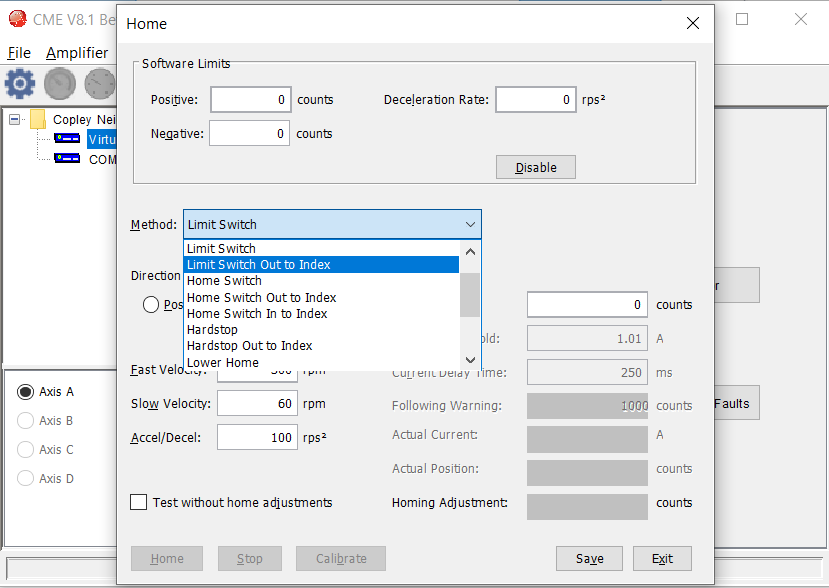
10. Configure Homing (if applicable)
Primarily in position or current controlled applications where you need to use a homing routine to set your 0 value. You can click Home on the main page to to configure this. There are options for using limit switches, other switches, hard stops, etc..
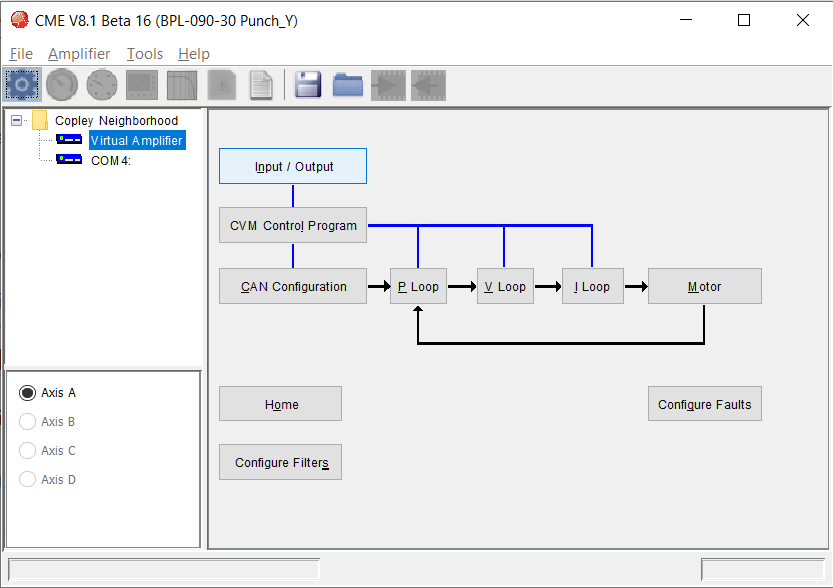
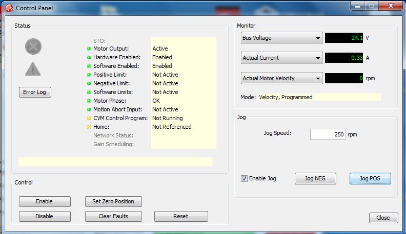
11. Check Main Control Panel
We finnaly get to try and drive the motor. This next step allows us to see any faults, check settings, and drive the motor.
Select Amplifier->Control Panel (You can also click the gauge icon to launch the control panel)
- Check if an error conditions exist
- Test estop and/or STO by seeing if the Hardware enable light toggles green to red as estop is switched.
- Verify when manually moving motor (motor should be disabled) the encoder value changes correctly
If you need to change the command mode (position, velocity, current) that is used in the control panel, rerun the setup and change the control method.
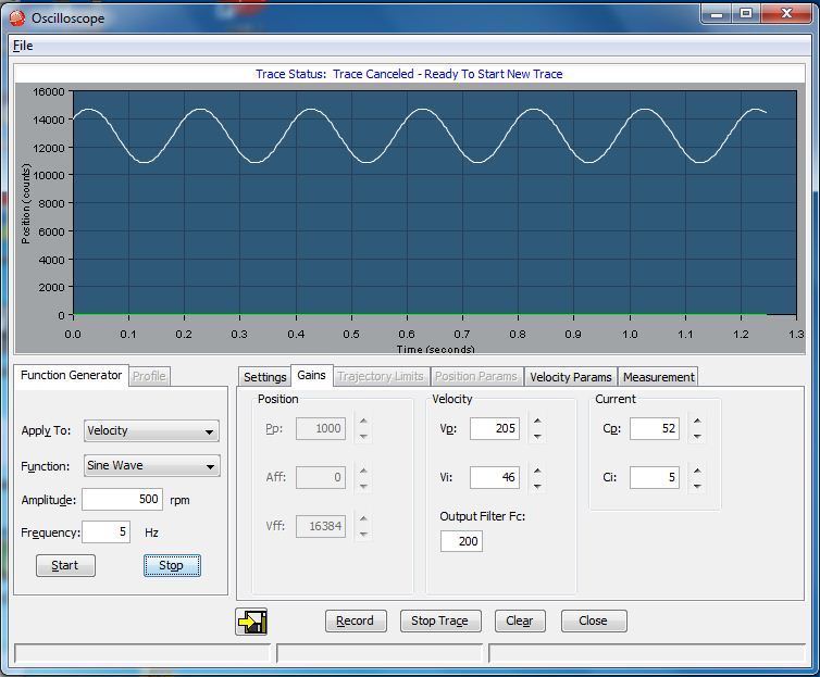
12. Motion tuning with the scope
Now that we have basic motion established above we can tune our controller. This is done on the Amplifier – > Scope page. This will let us send commands and view the response. We can also change gains and acceleration/deceleration profiles from this page. Actual tuning is outside the scope of this article, but I’ll give a few tips below and see the videos below.
- One tip is to start tuning at the lowest level and work your way up. So first verify current loop, then velocity loop, then finally position loop (assuming you are doing position control).
- Another tip is is to set the I term to 0, while tuning the P term to get the velocity level you want. Then you can increase the I term to reduce any steadystate error.
13. General Testing
Now that the system is tuned, go back to the Amplifier->Control Panel page and drive the motor at various loads and speeds to make sure everything is running as desired.
Congratulations! Everything should be working now. If not see the troubleshooting section below.
14. Save Configuration
Now that everything is working remember to save the settings to the flash on the controller and also to a file on your computer as a backup.
Having both the motor file and this configuration file saved for use on other controllers can make initializing multiple controllers a lot faster.
Troubleshooting
- Connection Issues:
- Is the drive powered and cables connected? Do you see lights on the drive?
- If not check power and cables.
- Also make sure your power supply had the voltage set properly and the current limit set properly
- Check if the interface exists
- Windows: check Device Manager
- Linux: check /dev/ for your device, and also check permissions of the device
- If using CAN, is the termination correct
- Is the drive powered and cables connected? Do you see lights on the drive?
- Motor not spinning issues
- Check e-stop/enable
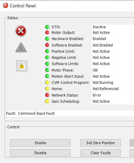
- Check the Control Panel in the interface to check for errors
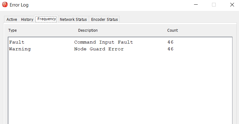
- Check the Amplifier->Error Log tool in the interface to see active and historical errors.
- Odd Motions (maybe with an abrupt stop)
- Check if gains are tuned properly. Try reducing the gains to get things under control.
- Are you also getting following errors?
- Check current limits
- Make sure motor can spin properly
- Make sure your commands are in a valid range
- Motors stop randomly with no apparent errors
- Add debouncing (from the Input/Output page) to your enable (or other inputs) that might affect the motion of the drive
Here is a video for more troubleshooting tips:
Disclaimer: While it might sound like Copley sponsored this post, they did not. I wrote this on my own to help a bunch of people that I know are using these drives and need help bringing systems up from scratch. Arguably Copley should have a bring-up wizard that guides people through the steps above.
I hope you find this useful, please leave comments below.
What did I forget to include? Tell me below.