
This post is part of the Hands on Robot Design series. See here for the full list of posts/topics http://robotsforroboticists.com/hands-on-ground-robot–drone-design-series for information on mechanical, electrical, motion control, computing, sensors, and more.
Once we had a drone we needed the sensors and computer to make this drone operate. Keeping with the idea of trying to make the drone as light as possible (and not caring about aesthetic) the payload was build with weight minimization in mind. The payload was mounted to the carbon fiber tubes near the front of the drone. On the two vertical sidewalls, one of the side walls was dedicated to the power electronics and the other side wall was dedicated to the computer. The computer ran all of the autonomy and control software for the drone as well as the object detection. To assist with object detection an Intel compute stick was also used. The main computer was an Intel NUC i7.
Payload Sensor Specification:
Velodyne (VLP-16) Puck Lite
Xsens MTi-200-VRU-2A8G4 IMU
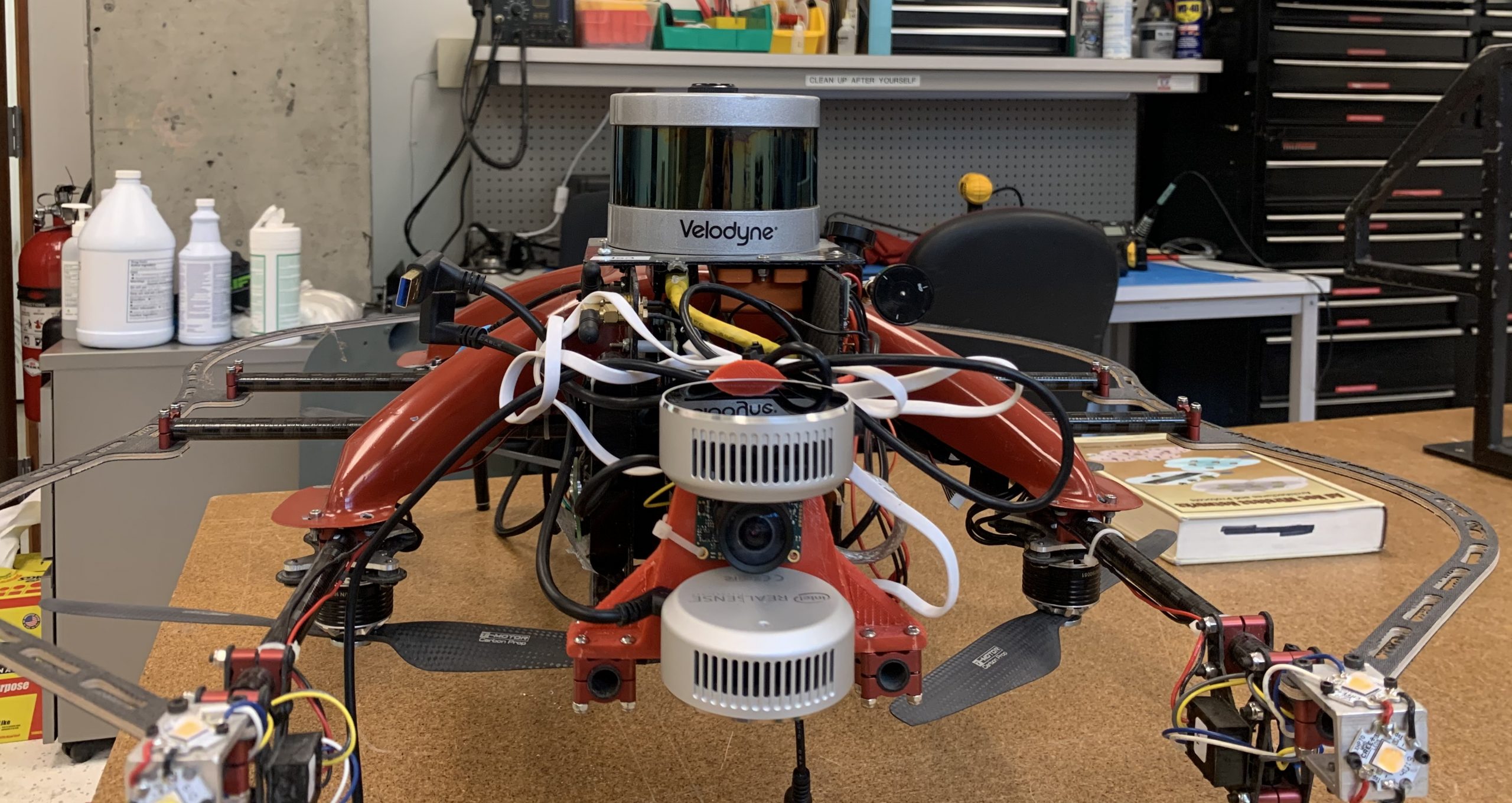
Intel Realsense L515 (x2)
UEye UI-3241LE-M/C RGB Cam
CozIR®-LP3 1% CO2 Sensor
Intel Dual Band Wireless-Ac 8265 W/Bt WiFi (For WiFi and Bluetooth device detection)
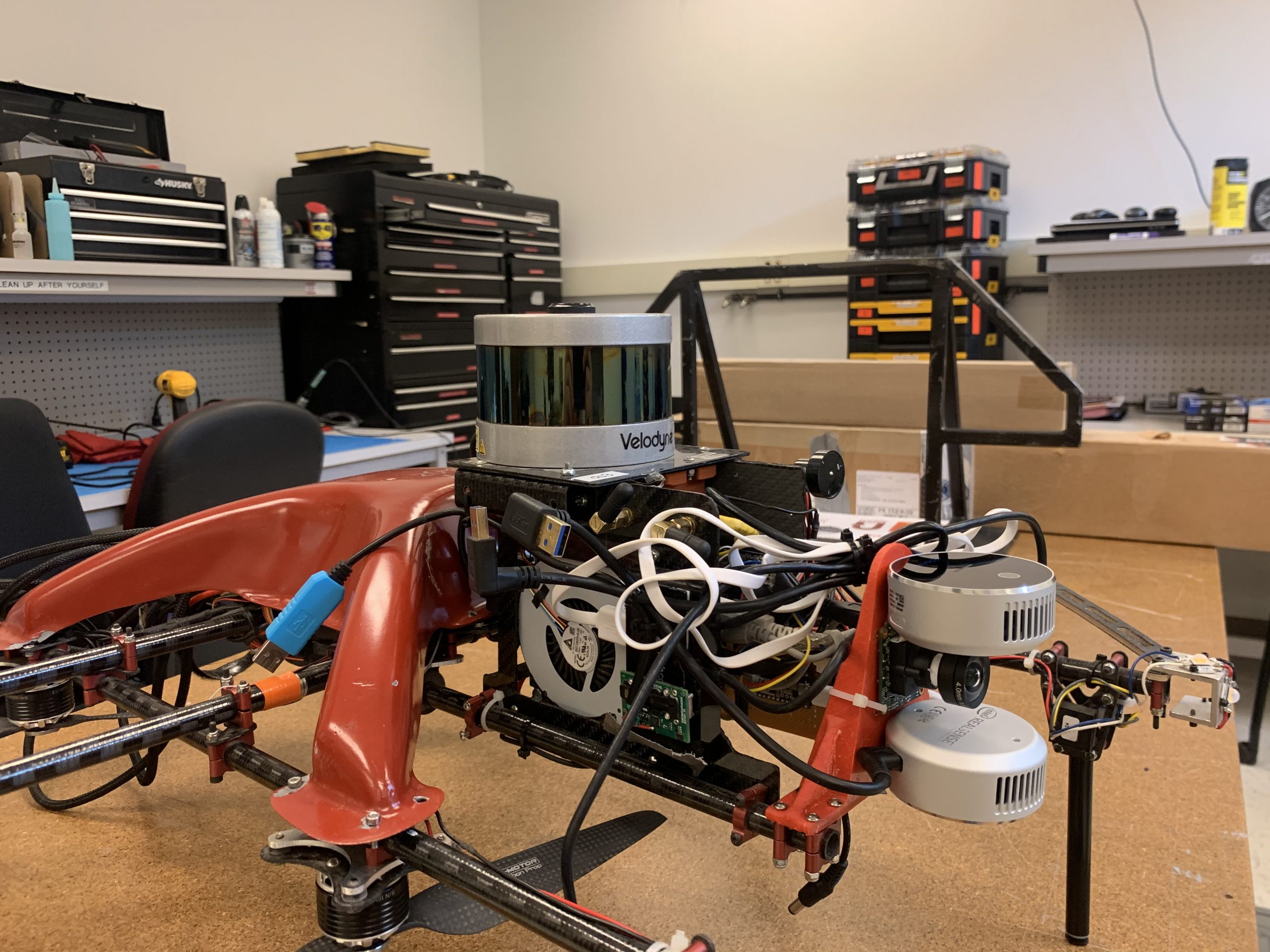
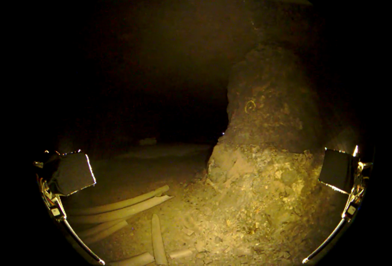
For exploration mapping and localization (SLAM) the Velodyne VLP16 Puck Lite LIDAR was the primary sensor. Realsense L515’s RGBD cameras were used both for helping with vertical localization (these were particularly useful for ascending/descending in vertical shafts) and object detection . The uEye visual camera (mounted between the Realsense cameras) with a fish eye lens was the primary sensor used for object detection to find the required artifacts in the subterranean environments.
In order to improve mapping and localization the Xsens IMU (small orange box) was mounted rigidly directly below the Velodyne (upside down).


A Teensy 3.2 microcontroller was used for various auxiliary tasks. The primary task was for time synchronization between various sensors. These sensors included the IMU, Velodyne and the trigger for the camera. The Xsens IMU was configured to send out a pulse per second (PPS) signal. This signal went directly to both the Teensy (via an interrupt) as well as to the PPS input of the Velodyne Puck. The Teensy would report that PPS signal (as well as an NMEA message for Chrony) to the computer via USB (yes, I know USB is not ideal for this) for time synchronization and also use it to generate camera trigger pulses for the uEye camera at 30Hz.
In addition to the time syncing, the Teensy had several other tasks including:
- Controlling the LED lights on the drone (when receiving a message via USB)
- Reading from the gas detection sensor and publishing the data via USB at a given frequency
- Controlling the relay that triggered the latch that connected the drone to the ground robot and was released before taking off from the ground robot (when receiving a message via USB).
I hope you enjoyed this post. Please leave comments below with any questions you may have.
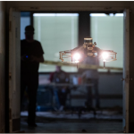
Main image source: https://www.cmu.edu/news/stories/archives/2021/september/darpa-subt-challenge.html