

This post is part of the Hands on Robot Design series. See here for the full list of posts/topics http://robotsforroboticists.com/hands-on-ground-robot–drone-design-series for information on mechanical, electrical, motion control, computing, sensors, and more.
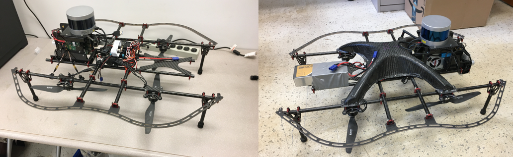
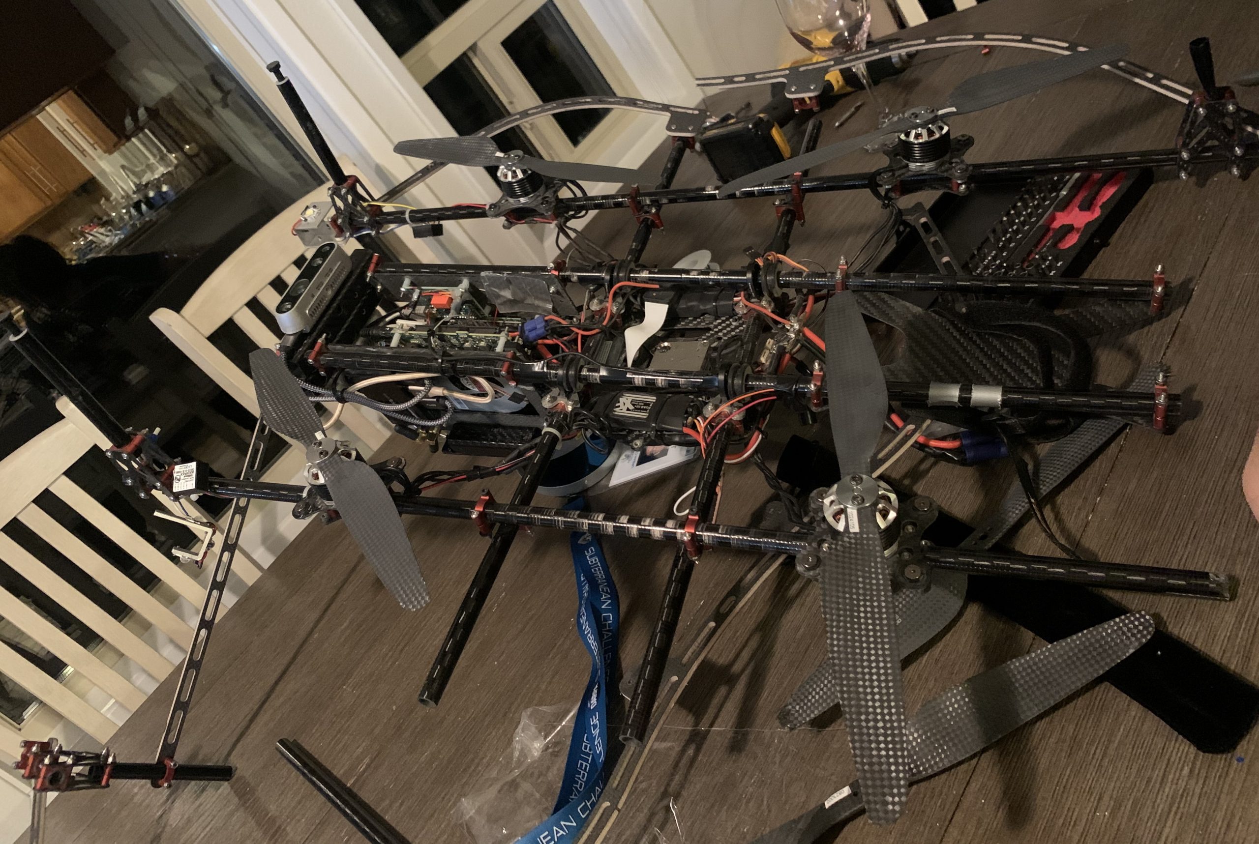
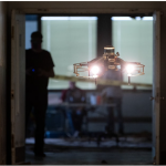
The drones designed for the DARPA SubT challenge needed to be great at flying through tunnels and exploring unknown subterranean environments. The plan was to be as aggressive as possible in order to explore difficult environments as fast as possible. The downside to exploring aggressively was having lots of crashes during testing. In order to recover from these crashes we used a modular frame where any part can be easily (some parts easier than others) swapped if it got damaged. This custom drone was purpose built and excelled in these environments. It was an inherently unstable drone that required an experienced human pilot or automatic controls to operate.
We had multiple drone designs, this design was names “Drone Small” hence we named them DS#, where # was the ID of the drone that we built. We built 4 drones.
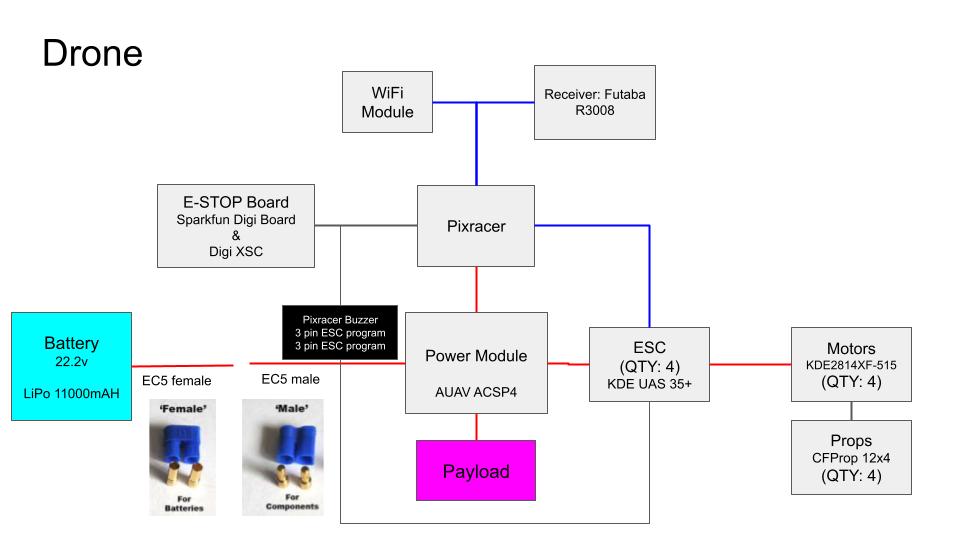
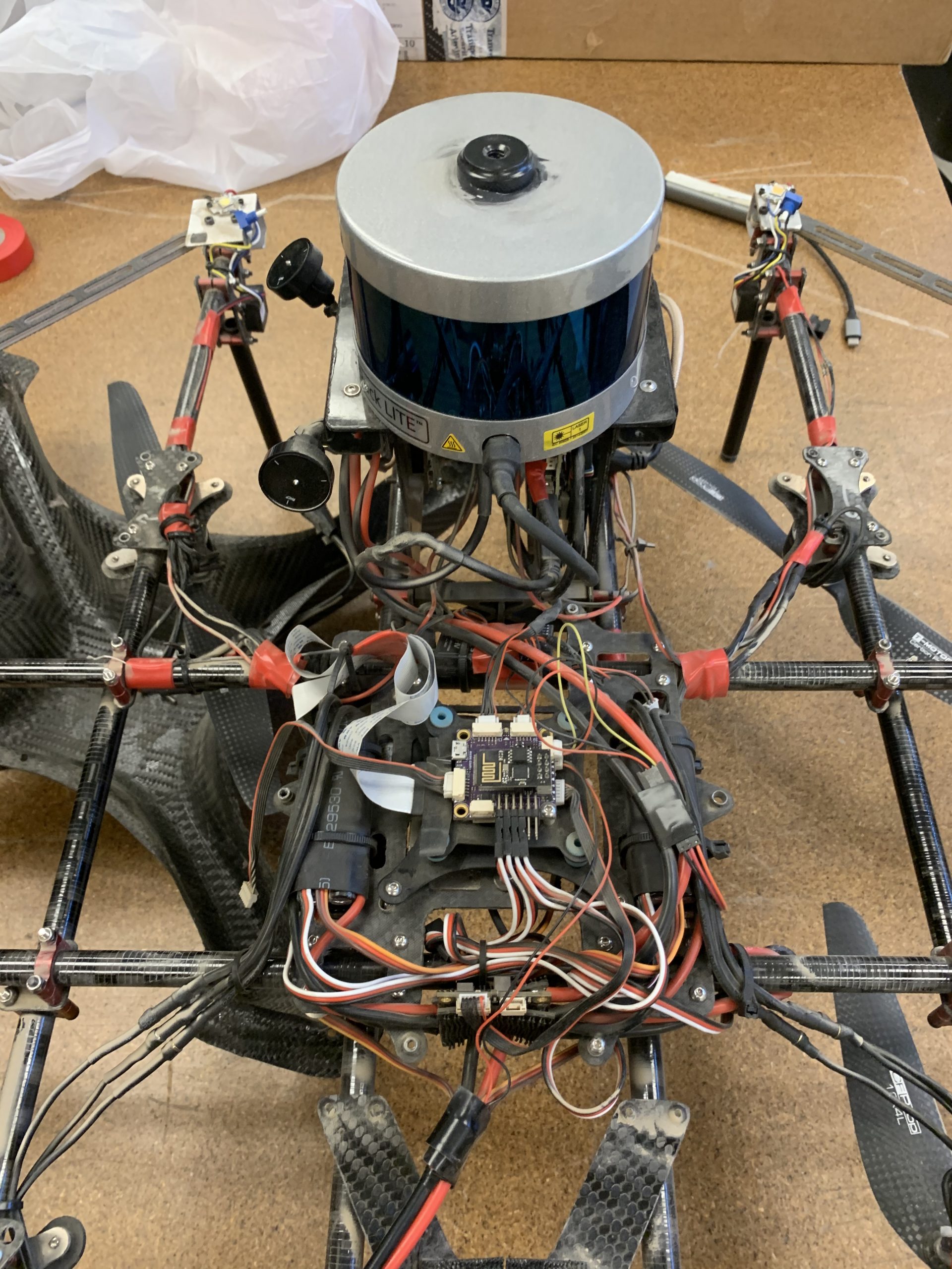
The heart of the drone was the Pixracer controller (actually it was the payload, but that’s for the next post). The Pixracer controller took commands from the computer in the sensing payload and executed them. From there, the Electronic Speed Controllers (ESCs) would commutate the motors. The motors had to be replaced every few months during testing due to dust ingress and the wear and tear on the internal bearings (yes I know you can replace the bearings, but they never worked as good as new after a few months.) We determined when to replace the motors based on an observed reduction in thrust.
Initially the drone was developed without the top cowling. However this cover/cowling ended up being needed to increase rigidity in the frame. A few times we saw poor drone performance and were able to trace it back to increased vibration from the cowling mounts to the frame being loose. The cowling was a custom carbon fiber layup that mounted to each of the 4 motor mounts as well as the center section.
The solution we developed had the following specifications:
Specifications

Type:  Custom Quad-rotor X-frame
Size: 830(L) x 770(W) x 350H) mm
Weight:  6.2 kg (13.7 lbs)
Power:   326 Wh (22000 mAh, 14.8V 4S LiPo)
Speed:   5+ mps
Endurance:  13 min
As we started flying faster through increasingly small openings it became clear that better prop guards were needed. The initial design had prop guards just right above the props, but we had to add prop guards below the props as well. The prop guards were made from a thin carbon fiber with a birch core. In addition to the “hard” prop guards we wrapped a string in the front and back to bridge the prop guards to increase the ability to “bounce” off from items and not cause the drone to crash. We did place both the upper and lower prop guard close to the props in order to minimize changes in attitude when colliding with surfaces. This prevents the drone from needing to aggressively correct which would often lead to saturating a given motor.

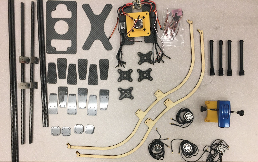
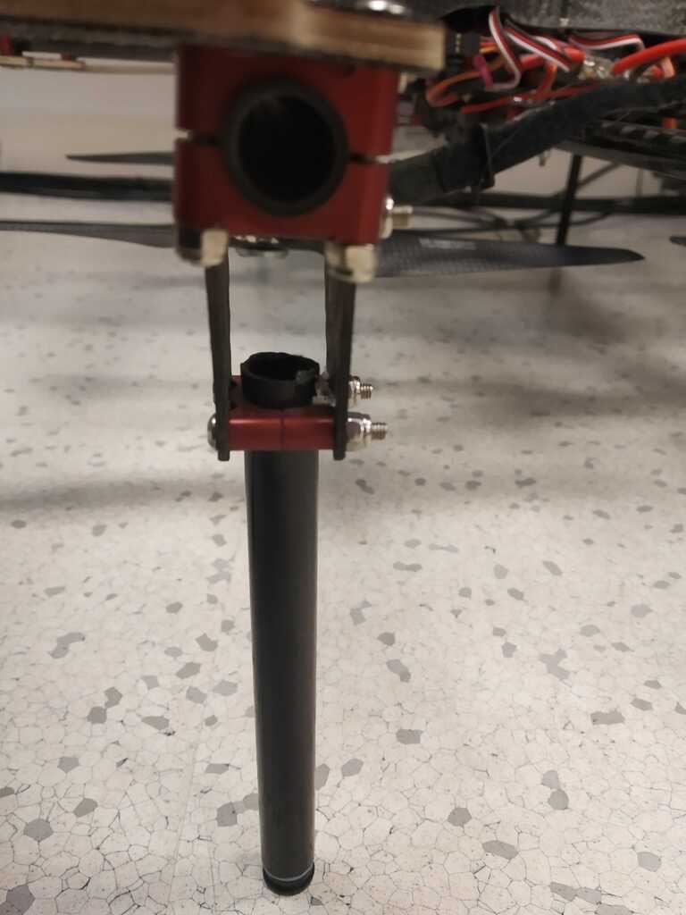
Here is the tubing that was used https://www.rockwestcomposites.com/round-tubing/round-carbon-fiber-tubing/intermediate-modulus-tubing/46401-im-group The tubing got cut to 2 x 30” tubes, 2 x 24” tubes, and 2x 22” tubes.
Here is the material used for the prop guards https://dragonplate.com/dragonplate-carbon-fiber-birch-core-3_16-x-24-x-48
Click here to continue this post and read about the sensor payload
Main image source: https://www.cmu.edu/news/stories/archives/2021/september/darpa-subt-challenge.html

Pingback: Hands On Ground Robot & Drone Design Series - Robots For Roboticists